Summary
This document discusses installation testing for the build phase of a typical FTTH Passive Optical Network (PON) cable plant using a connectorized splitter with particular emphasis on an external centralised splitter architecture. We discuss the purpose of testing and the function of typical build phase test instrumentation.
We posit that the PON network can be divided into several logical sections for testing purposes and that the sectional testing solutions are dependent upon the required Quality of Service
Definitions
Within the industry there is a proliferation of terms and acronyms in use for a given network element. Further subtle variances in definitions may exist between differing administrations. The following generic definitions are used in this document.
| APC |
Angled Physical Connect |
| CAPEX |
Capital Expenditure |
| DSL |
Digital Subscriber Line |
| FDH |
Fibre Distribution Hub. Aka |
| LCP |
FIT Failure in Time. Typically, 1 failure in 109 hours. |
| FTTH |
Fibre to the Home |
| FTTx |
Generic for several types of Fibre delivery systems. |
| Head-End |
Carrier building where the network signal distribution starts. |
| ITU |
International Telecommunications Union |
| LCP |
Local Convergence Point. Aka FDH |
| MCSM |
Matched Clad Single Mode |
| MTBF |
Mean Time Between Failure |
| MTTF |
Mean Time to Failure |
| MTTR |
Mean Time to Repair |
| NAP |
Network Access Point |
| NID |
Network Interface Device |
| NMC |
Network Maintenance Centre |
| OLT |
Optical Line Terminal |
| ONT |
Optical Network Terminal. Serves one customer. See also ONU. |
| ONU |
Optical Network Unit. Serves several customers. See also ONT. |
| OPEX |
Operational Expenditure |
| ORL |
Optical Return Loss |
| OTDR |
Optical Time Domain Reflectometer |
| P2MP |
Point to Multipoint optical system |
| P2P |
Point to Point optical system |
| PON |
Passive Optical Network |
| POTS |
Plain Old Telephone Service QoS Quality of Service |
| ROI |
Return On Investment |
| VLS |
Visible Light Source |
Further information on terms relating to FTTx can be found in ITU-T Recommendation G.983.1 Broadband optical access systems based on Passive Optical Networks (PON) and the FTTH Council document Definition of Terms.
Why test?
Optical cable plant typically has a planned design life of 20-40 years. Transmission equipment life span may considerably less.
Transmission systems require installation testing to verify that variously:
- The network is correctly configured and is fit for use.
- The network is built to specification.
- Proposed transmission equipment performance limits are met.
- The installation is proven to meet manufacturer warranty requirements.
- Required information is gathered to facilitate future maintenance.
- Construction contractual obligations have been met.
- Operational reliability promises can be met.
Failure to adequately test to an acceptable level during construction will randomise CAPEX whilst maximising OPEX and customer dissatisfaction. Put another way: inadequate testing is expensive.
To achieve “adequate” testing in this situation requires careful consideration. It’s quite possible to achieve “adequate” testing at modest cost, however incorrect planning will result in inadequate testing at a much higher initial cost.
Who tests?
This is an important issue, since in the currently anticipated FTTH scenario, and for lowest cost, it must be done on-site by relatively less skilled personnel than has traditionally been the case, so testing must be simpler to perform and interpret. Test equipment requiring specialised skills can’t be used, except by a specialist 2nd tier response crew.
Pre-installation testing
We introduce this concept here, because it’s an important part of a QA and risk containment strategy, particularly if (when) some network element is found to have a high as-delivered fault rate, and therefore requires extra testing, or some high level of risk is associated, e.g. cable qualification prior to installation. Given the nature of PON installation, it’s obviously a lot cheaper overall to ensure such testing is properly done and documented prior to site delivery. This could be done by the network operator, installation contractor, 3rd party, logistics supplier, vendor agent etc. The important thing is that it is done, and as part of an overall QA plan. It will save money, time, and boost the operator’s brand image.
PON architectures
A PON network is a Point to Multipoint (P2MP) architecture servicing many low revenue (typically domestic) customers. Testing is more complex than in traditional Point to Point (P2P) because a given customer’s circuit is composed of both shared and dedicated fibre. Indeed, the increased test complexity, combined with greatly increased cost constraints, means that testing needs to be very carefully evaluated and implemented.
PON networks use passive splitters to distribute fibre to individual homes. One fibre is optically split into 16, 32, or 64 fibres, (128 under investigation) which are then distributed to residential or business subscribers. The switching and routing are done at the carrier's central office.
Once on the customer's premises, the fibre connects to a Network Interface Device (NID), called variously an Optical Network Termination (ONT) or an Optical Network Unit (ONU). This device converts the optical signal into a format that can be used directly by the customer.
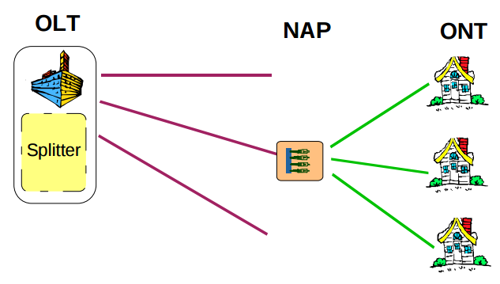
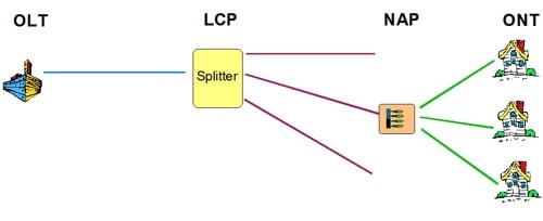
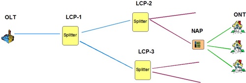
PON networks can be configured in one of three types of access topologies.
- Head End splitter, also called Central Switch.
- Single LCP splitter, also called Local Convergence.
- Multiple LCP splitters, also called Distributed Splitting or Cascaded Splitting.
At time of writing, there is no agreed upon naming nomenclature.
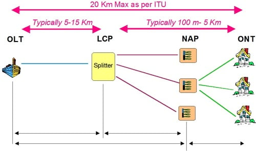
These configurations are shown in the Figures 1 below with Figure 1B being the most common implementation and that which is used within this document.
PON access proposals
There are several PON protocols and standards defined by the ITU organisation with varying levels of maturity. The three main ones, at time of writing, are BPON, EPON and GPON. Table 1 below illustrates their main features.
| |
BPON |
EPON |
GPON |
| Standard |
ITU-T-G.983 |
IEEE 802.3ah |
ITU-T G.984 |
| Upstream λ |
1310 nm |
1310 nm |
1310 nm |
| Downstream λ |
1490 & 1550 nm |
1550 nm |
1490 & 1550 nm |
| Protocol |
ATM |
Ethernet |
ATM, Ethernet, TDM, GEM |
| Bandwidth |
Down ≤ 1.24 Gbps
Up 622 Mbps |
Down ≤ 1.25 Gbps
Up ≤ 1.25 Gbps |
Down ≤ 2.4 Gbps
Up ≤ 2.4 Gbps |
| Max Distance |
20 Km |
10 or 20 Km |
10 or 20 Km |
At time of writing, the ITU and IEEE are working on a ‘next generation’ 10Gbits/s PON standard.
What QoS?
What Quality of Service (QoS) is required? A simple question that doesn’t seem to get discussed, and doing so yields some useful answers, so we attempt to tackle it here:
The reliability performance of a transmission network can be calculated by the well-known unavailability formula:
| μ= |
MTTR |
≈ |
MTTR |
≈ |
MTTR * FITs |
| (MTTF = MTTR) |
MTTF |
109 |
Where MTTF is Mean Time to Failure, MTTR: Mean Time to Repair and FIT is Failure in Time with 1 FIT = 1 failure in 109 hours.
Availability, α is simply 1-μ.
Traditional P2P networks may typically have an availability of circa 99.9% or higher. That is, a down time of less than 8.8 hours/year. Where greater reliability is required
equipment duplication and ring topologies, often in conjunction with geographical isolation of the cable path are employed, at of course, additional CAPEX.
PON networks, however, are per unit customer, low revenue. A lower availability may therefore be acceptable. But what should it be?
The reliability issue is usually also affected by 3 key factors:
- Performance of automated service fault reporting systems
- The Mean Time to Repair (MTTR) a fault
- Customer Service Level Agreements
One suggestion is that the acceptable availability should be not less than that for a Plain Old Telephone Service (POTS) or DSL service. Another is that it must be higher due to video service delivery. What is the availability of your POTS/DSL? What are your customers’ expectations?
From surveys we have done on FTTH equipment and installed cable plant reliability, the reliability of the customer’s ONT is likely to be a practical limiting factor, on service reliability.
We arrive at this conclusion from the following data:
- ONT manufacturers’ web sites typically quote an MTBF of 10 years.
We also assume that fibre cable system reliability is:
- A “traditional” fibre cable, using proven best practice materials & installation practices, seems to achieve a typical intrinsic installed cable MTBF of 1 failure / year / 3,000 fibre-Km. This figure of course ignores the main causes of failure, being human intervention, storm & tempest.
Consider what we arrive at if the cable intrinsic MTBF is allowed to be 30 times worse and the average length of the PON is assumed to be 5 km:
- New fibre MTBF = 100 Years/Km
- PON fibre MTBF = 20 years/5 Km (FIT = 5,850)
Another way of expressing this is one fibre failure a year for every 100 Km of fibre, which is significantly less than the rate of accidental cable damage in an urban
environment.
The importance of these simple assumptions is as follows:
- Given the widely varying MTBF’s, the ONT is the limiting factor for service reliability.
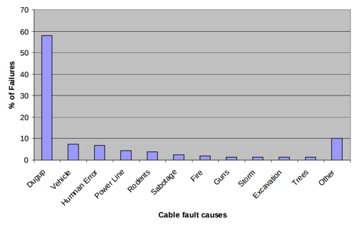
- The fibre cabling doesn’t need to be very well installed to achieve a very acceptable level of service reliability as most cable faults are man-made. Table 2 below shows typical causes of fibre failures in an urban environment.
Installed cabling reliability can be of the order of 30 times worse / km than traditional best practice with minimal QoS impact in a PON environment.
Where to test
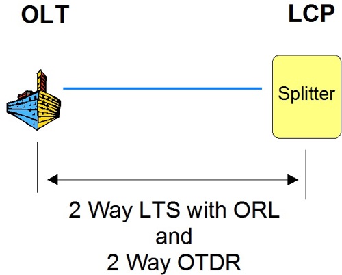
When the splitter is located at the Head-End, (Fig. 1A) traditional P2P testing techniques are applicable. This architecture presents the simplest testing regime.
If one of the field-based LCP splitter options is chosen, which is the norm, testing must be performed at two or more locations to adequately characterise the transmission link. This of course increases testing complexity and costs.
Let us consider the testing requirements of a PON configured with a single external LCP. (Fig 1B)
To adequately characterise the installation, testing is required between the following network components:
- Head-End to LCP
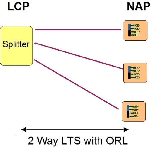
- LCP to NAP
Possibly the Drop cable, which connects the NAP to ONT. More on this later. These are shown in Figure 2 below.
As can be seen, unless care is taken the cost of testing can be quite expensive relative to income. This is especially so when one factors in the potential for many installed
fibres to lie unused and a customer’s expectation of rapid service activation.
Build phase test instrumentation
Several instrument types may be considered to perform PON installation tests as shown in Table 3.
| Test Measurement |
Instrument |
Purpose of Test |
Test Complexity |
Price Range
USD |
| Connector |
Microscope |
Check contamination!
Check end face quality
|
Easy |
> 300 |
| Fibre Identification |
VLS
Fibre Identifier
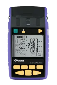
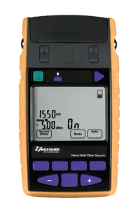
Source & Meter
|
Identification of designated fibre |
Easy –
Medium |
600 -2,500 |
| Section Loss |
Source & meter or Loss Test Set |
Section loss of the cable
Pass/Fail evaluation
Warranty
|
Easy |
> 3,000 |
| System ORL |
ORL meter / LTS |
Ensure ORL is within design parameters. E.g. ITU-G-983 |
Easy –
Medium |
> 7,000 |
| Cable characterisation |
PON OTDR |
Physical fault location
Loss & reflection at joints
|
High to very high |
> 16,000
|
| Splice Loss |
Splicer |
Check Splice Loss |
Easy |
7,000 |
| Optical Power |
λ Selective Power Meter |
Check Transmission Power |
Easy |
> 1000 |
| Faulty NID |
NID Diagnostics
Spare NID |
Determine if NID has a fault |
Easy |
0, but operator costs at NMC |
| Triple Play Test |
Other |
Check the 3 services delivered to the customer |
Medium |
> 4,000 |
| Head Room |
In line attenuator |
Determine if design transmission margin met
|
Easy |
< 10 |
Some pertinent aspects of these test instruments are discussed below.
Microscope
Traditional optical microscopes with 200x magnification and an optical safety filter are cheap, adequate, and easy to use. However, some users now favour electronic video scopes since they allow recording of image data, are intrinsically optically safe and can be used to inspect installed bulkhead connectors. They are also about 10 times the cost, less reliable and require more skill to use. The decision here is probably about how much the operator is trusted. Simple training is needed to focus and recognise good / bad connector condition (pictorial).
Visual fault finder light source
Visible Fibre Light sources provide a red light of circa 635 nm wavelength. Useful for finding open circuits in patch leads or splices, for locating fibre ends, and generally checking continuity. Maximum range is dependent upon several factors but is in the order of 5-7 Km.
This is a very favourite craft tool for both skilled and unskilled field staff. It’s very easy to use, and very effective on these shorter links. It won’t do much on fibre length over about 5 Km, for which another solution is needed. Most useful where the fibre ends are accessible, which may make it of limited use when re-entering a live system.
Simple hands-on training is needed to learn how to bend a fiber to make it glow. As PONs use APC connectors, an APC-PC adaptor patch lead may be required to match the VLS connector. –Refer Section 7.2 ORL for cautionary.
Fiber identifier
Also known as a traffic identifier. Works over the full 20 Km PON length and allows the user to see if there is a live signal, test signal, or no signal in a fibre before re-entering a live system, or as a long range fibre identifier. Typically used with a test light source, which is used to produce an optical test tone. Simple hands-on training is needed.
The use of a fibre identifier when working on live cable is mandated by many network owners to minimise costly outages.
All fibre identifiers create a small loss on the fibre when in use. This loss is often overlooked by some system designers who produce designs with minimal ‘head room’ or ‘system margin’. Failure to allow sufficient ‘head room’ for foreseeable maintenance activities can have disastrous results.
Table 4 below, shows some typical published insertion loss figures for a popular brand of Fibre Identifier.
|
Wavelength
|
Insertion Loss
|
|
1310 nm
|
0.01 dB
|
|
1550 nm
|
0.11 dB
|
|
1625 nm
|
0.31 dB
|
Be aware that there are brands on the market with lower insertion losses. These come at the price of being rather insensitive!
Source & meter / Simple loss test set
Used to test end to end loss, and as a continuity tester if equipped with a tone detector function. The source can also be used as a tone source for a clip-on fibre identifier. The meter can also be used to measure transmitter power, however this function is not so useful for this here, since a wavelength selective meter is needed. Consideration may be needed as to how test results will be recorded, since in practice data recording / manipulation can be over half of the testing cost. Some theoretical and practical training is required.
Two Way & ORL Tester
Does the job of a source and meter / simple loss test set, but it can greatly simplify accurate testing if it can perform bi-directional loss and additional ORL testing in one go. Consideration may be needed as to how test results will be recorded, since in practice data recording / manipulation can be over half of the testing cost. Some theoretical and practical training is required. A pass/fail function may be available.
This equipment is the simplest and fastest method of certifying the cabling system.
OTDR
OTDRs have limitations which are normally not of great concern. However, in splitter based PON network there are various significant problems as follows:
- The splitter is a cause of severe Event Dead Zone limitations.
Consider a 32-way splitter, then when operated in a mode which overcomes the 18 dB splitter loss, say to achieve about 25 dB dynamic range, a modern FTTX OTDR will have a pulse length of 1 – 10 μsec, giving it a substantial dead zone of 150 m – 1.5 Km. That’s a long way in an urban environment!
- They cannot properly characterise cable downstream from the splitter as any discontinuities cannot be uniquely identified. Some limited level of performance can be achieved with low split ratios.
- Experienced OTDR operators who really know how to optimise the OTDR settings for dead zones etc, are uncommon. In a PON, this knowledge is critical.
- Another distinct problem is difficulty of analysing the trace. The automated analysis doesn’t always work, and this is one of the hardest jobs in fibre measurement, requiring substantial theoretical and hands-on training and experience.
To us, this expensive instrument looks best left to the specialist back-up crew, as an aid to troubleshooting. In fact, this instrument is a major reason why you would have such a team.
The essential limitations are well documented in available literature. An early reference is Optical Time-Domain Reflectometry, by Duwayne Anderson & Florian Bell, Chapter 10.
There is another issue here which is currently appearing: Cable and Fibre types are being developed which are very insensitive to bending loss. Improved G.652D compliant cable meeting the ITU’s recently introduced recommendation G.657, Characteristics of a Bending Loss Insensitive Single Mode Optical Fibre and Cable for the Access Network is available now.
The G.657 standard describes two types of bend-improved optical fibers. The first is referred to as Class A single mode fiber that is fully compliant with the embedded base of G.652D low-water-peak fibre.
The second G.657 fiber type is referred to as Class B and was included in the standard to target the niche application of wiring within residences, though some Class A fibers can also support this application. The Class B recommendation encompasses existing and proposed bend-insensitive fibers that may not be compliant with the embedded base such as hole-assisted fibers and fibers with very small mode-field diameters.
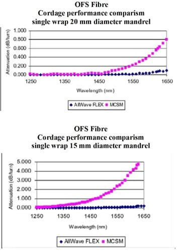
These bending insensitivities are demonstrated in Figures 4 & 10 below.
On the reasonable assumption that G.657A fibres will become common, then the practice of using loss or OTDR testing to identify cable stress points will need re-evaluating as it will be unlikely to show much.
Splicer
This isn’t usually regarded as test equipment, but when it’s an auto-alignment type, it has a built-in loss estimator that can form a useful part of an overall PON test strategy. If a splice passes the loss estimation check, it would be good enough for use in a PON. This is a zero-effort, zero-training test! Most splicers used by cable crews are auto-alignment types, since they cope with field conditions much better than fixed v-groove types.
Wavelength selective power meter / ONT diagnostics / Spare ONT
A Wavelength Selective Power Meter is required for transmission power testing. First, it is required to measure the 1490 / 1550 nm power transmitted at the head end. Second, it is required to measure the much lower power 1490 / 1550 nm levels at the ONT at service turn-up.
The currently topical requirement for an in-line meter for service turn-up and maintenance seems problematic to us, based on the following logic:
- If there is a problem with the cabling plant, then an in-line meter isn’t needed to find it.
- If the 1490 / 1550 nm power levels look OK, then either the ONT has a problem, or the fault is upstream from the ONT.
- The obvious thing is to examine available ONT diagnostics and if necessary, sectionalise the fault.
- If the fault is in the ONT, then exchange the ONT. In this case, a spare ONT forms an integral part of the test/repair strategy, and a crew would presumably have one anyway.
There are of course, some important issues with how the carrier’s operational support systems interface to the field staff in a timely manner during maintenance and service activation.
Triple play test
We assume that at service turn–up, the greatest challenge for the field crew will be to get all the customer’s “triple play” equipment (phone system, internet connection, video) to work properly with the ONT, since it’s likely to be different with each customer. However, this is outside the scope of this paper.
Section loss
Physical loss over a section of fibre. This is measured with a source and meter at 2 or more wavelengths, or preferably, with a bi-directional loss test set which incorporates Optical Return Loss (ORL).
System ORL
The requirement to measure ORL in a PON seems to be open to debate. ORL induced problems have diminished since the widespread adoption of APC connectors, isolated lasers, and digital transmission, all of which, if applied properly, tend to make ORL something of a non-issue. However, in the event of a transmission problem, it may need checking, and can be tested with negligible effort using a suitably equipped two-way tester. The classic problem is that someone accidentally leaves an unterminated PC connector somewhere on a system, which then mysteriously misbehaves.
If a transmission system’s minimum ORL requirements are not met the transmitted data may be corrupted resulting in increased noise and or system failure. A general rule is that:
- Analogue transmission systems are more affected than digital.
- Digital systems become more prone at higher data rates.
Cable characterization
In this situation an OTDR can be used to evaluate the as built characteristics of the installed cable plant and locate faults. Typically testing is performed at 2 wavelengths to be able to identify any bending violations
As previously discussed, with the advent of G.657 fibre, traditional OTDR testing must be re-evaluated. The use of a higher wavelength pair than 1310/1550 nm will be required to identify stress points in such fibre.
It must also be noted that inherent with the use of bend insensitive G.657 fibre is the need to ensure that the cable construct itself also permits greater bending.
OTDRs also provide an estimate of the cable section loss and ORL. To measure the actual section loss as will be seen by the transmission equipment, a light source and power meter combination or Loss Test Set must be used. Similarly, an ORL meter is required to measure the ORL that will be seen by the transmission equipment.
Test wavelengths
The cable needs to be loss tested at all three PON wavelengths, 1310, 1490 & 1550 nm. Right? Well not necessarily. If an installation passes at 1490 & 1550 nm or 1550 & 1625 nm, how can it not pass at 1310 nm?
Recently, modestly priced testers at 1625 nm have become available. Many network owners are now beginning to mandate testing at this wavelength due to the several advantages that 1625 nm offers, such as:
- Out of band in service monitoring and testing.
- More sensitive to fibre anomalies such as bending violations. (Important for G.657)
- Early detection of cable faults.
There is certainly a need to test at least two wavelengths, to identify serious bending violations.
That said, modern loss test sets, generally incorporate an Autotest or automatic wavelength toggling capability, thus the extra time to perform a loss test at all 3 wavelengths is insignificant.
It is strongly suspected that if loss testing is done at 1625 nm (or even 1550 nm), then this is nearly as effective as OTDR testing at identifying if there is a serious cable bending problem (remember, we can survive 25 times worse cable reliability than traditional best practice). Such incidents can be expected to be relatively uncommon, and therefore it is justified to not keep an OTDR and operator on-site during general installation.
Testing solutions / Installation tests
There are three main components of the build phase field testing. These are:
- Pre-installation tests
- Installation tests – pre power up.
- Installation tests – post power up.
Items 1 and 2 are discussed more fully below.
Once work practices and reliability have been stabilised and proven, a sample test methodology could be considered, which could lower costs further.
Standard QA methodology includes various established statistical sampling methods, a detailed discussion of which is outside the scope of this paper.
We assume that any organisation that has reached the point of considering statistical sampling methods has therefore achieved a proven a level of installed reliability, which also implies that they have enough operational data to make proper decisions without reference to this paper!
Pre-installation tests
There is a tendency amongst many network builders to follow the ISO9001 paper trail requirements in a simplistic fashion.
A wise network builder, however, ensures that prior to installation, equipment and cables are inspected and possibly tested (by someone, somewhere) to ensure that they comply with the required specifications.
Failure to check as delivered equipment and cables can lead to costly rework and litigious warranty claims.
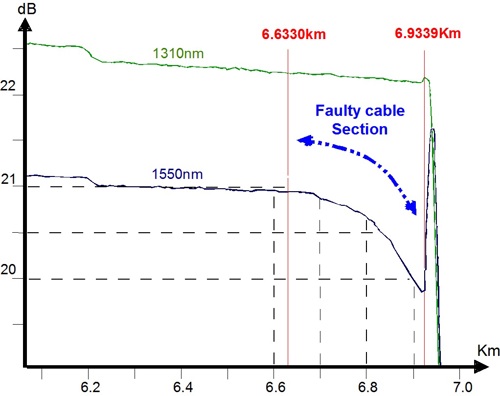
Example of consequences
Figure 4 below shows an OTDR trace of an optical cable showing distributed micro bending losses at 1550 nm due to a faulty cable manufacture.
- The cable manufacturer failed to test the cable after manufacture.
- The network owner failed to test the cable prior to field installation.
- The Field Project Managers failed to specify any loss testing prior to system power up.
The result of all these oversights was costly rework and many dissatisfied customers.
The following pre-installation acceptance methodology should be considered.
- Manufacturer to be required to provide factory test data.
- Clearly determine who is responsible for storage of ‘as supplied’ test data.
- Clearly determine access methodology for ‘as supplied’ test data.
- Network owner randomly test a selection of ‘as supplied’ product.
Especially:
- When a different supplier is used.
- When a new or modified design is introduced.
- When a mission critical installation is involved.
For cable, the recommended testing is:
- OTDR test 1 way on the ‘as delivered’, cable drum
- Testing at two wavelengths recommended.
- Test at least 1 fibre in every tube.
Installation Tests – Pre power up
As previously discussed, an optical fibre system must be tested so as to determine its fitness for service. This requires that various individual link loss parameters be measured.
Head-end to LCP
Typical characteristics of this section are:
- Low fibre count.
- Typically, 5-15 Km in length.
- May be either FTTx based or traditional services.
- Individually these fibres carry the greatest revenue in the PON.
- A failure of one PON fibre will affect all customers on its associated splitter, that is, up to 64 customers.
It is recommended that full testing be performed to adequately characterise the transmission link:
- Both-way link loss at a minimum of two wavelengths including ORL.
- Both-way OTDR at two wavelengths.
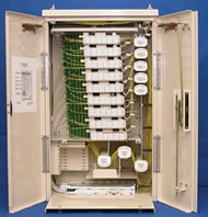
Optical splitter
Joining the Head-End fibre to the NAP fibres and located at the LCP, the optical splitter is a highly reliable device having undergone extensive manufacturer testing. Indeed, one manufacturer claims that of the 10’s of thousands shipped, none have ever come back!
If we accept this claim, and certainly anecdotal industry feedback backs it up, with FITs of between 1,000 and 775 being suggested, then a case can be made that the splitter itself does not need to be field tested for correct transmission performance.
Some confirmation testing will of course be required to confirm that the correct splitter has been connected to the correct head-end fibre. This can be as simple as injecting light from the Head-End and confirming the optical splitter output level at a specified port, say the first or last port is within specifications.
The risk is that of post-production connector end face contamination. This is typically caused by electrostatic dust attraction and plastic outgassing from the protective end cap. It is easily mitigated by adherence to standard inspection and cleaning procedures whenever the connector ports are accessed.
Typical splitter losses and output port uniformity are shown in Table 5 below.
|
Splitter
Ratio
|
Typical Loss dB
|
Output Uniformity dB
|
|
4
|
6.7
|
0.5 – 0.9
|
|
8
|
9.8
|
0.8 – 1.2
|
|
16
|
13.2
|
1 – 1.7
|
|
32
|
17.9
|
1.3 – 2
|
|
64
|
21
|
2
|
LCP to NAP
This cable runs from the Local Convergence Point (LCP) to all Network Access points (NAP) in the PON network, whilst there are many ways it can be built. Typical characteristics are:
- High fibre count. From 32 to over 2,000.
- Typically, 100 m -5 Km in length. Presumably not much splicing / jointing, or the splitter would be placed elsewhere?
- Individually these fibres carry the least revenue. A failure of one fibre will normally affect one customer.
- Many fibres may be unused for a relatively long time, due to vacant blocks, estate rollout timings, an all-mobile-phone household, etc
- Cable sections may be joined by traditional splicing, connectorized techniques or a combination of both.
Traditional both way OTDR and LTS testing on every fibre may be excessive when compared to individual revenue and designed QoS.
It is also expected practice that on odd occasions where a fibre is found to be not working, an alternative fibre will be used, rather than repair. This implies that spare access ports are to be provisioned in several of the NAPs. What is your acceptable % of faulty fibres in the cable?
Possibly, a sample test methodology could be considered at a later stage. In which case, should any test fail, testing can be escalated as required using standard techniques.
Where both connector ends available:
- Using a LTS (possibly with ORL), both way link loss of all connectorized NAP ports at a minimum of two wavelengths.
- Testing at two or more wavelengths preferred. Else test at one higher wavelength.
Advantage
- Minimises future rework.
- Section loss positively identified.
- Fibre transpositions will be found.
- Bad splices will be found.
- Faulty connectors and through-connects/adaptors will be found.
- Bending violations will be found.
- Any cable sections not yet provisioned to NAPs will not be tested.
- A matter of workforce timing. It is generally cheaper to fix faults whilst the cable install crew are not yet redeployed rather than have to recall them.
Disadvantage
Where only LCP connector end available
This may occur with for instance a delayed estate rollout.
- OTDR test 1 way from LCP towards NAP
- Testing at one wavelength recommended.
Advantage
Disadvantage
- If there are any fibre transpositions in the distribution cable, they may not be located.
- Continuity through to the NAP not positively identified.
- Section loss not positively identified.
- Restoration activities because of unidentified cable faults may adversely affect customer services and brand name recognition.
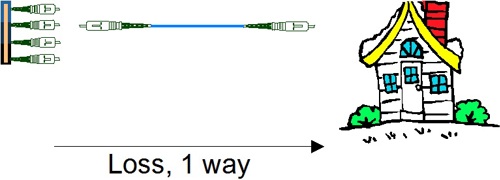
Drop Cable
This cable runs from the NAP to the customers Optical Network Terminal (ONT). Deployment distances are small being typically less than 100m. Over such distances, the fibre loss is negligible, connector losses dominate.
In recent years, spurred by the desire to minimise OPEX & CAPEX, there has been considerable development in drop cable design, including the introduction of a new ITU category G.657 to cater for them.
Recent innovations include:
- Bend violation resistant cable sheath designs.
- Factory assembled & tested pre-terminated cable.
- Bend optimised fibre. Refer Figures 10 below & 3 above.
- Environmentally hardened optical connectors.
- Connector pulling shrouds.
- Blown/ Pushed fibre.
As a result of these innovations and of course the short distances involved, several network owners are now using optically unskilled workers for the drop installation.
They are also asking ‘do we need to ‘test the drop cable?’ Unfortunately, there is no hard and fast answer.
From of a testing viewpoint, the several cable designs can be considered as pre-connectorized and other styles.
The relative advantages and disadvantages of the two types are discussed below.
pre-terminated off-the-shelf:
Advantages
- Factory assembled and tested prior to delivery.
- Fast installation.
- Minimal skill required.
- Cost of tooling low.
- Easily replaced, especially if underground installation in conduit.
- Minimal testing.
Disadvantages
- Increased cable inventory costs as must keep several standard lengths in stock.
- Need for provision of excess drop cable storage space.
- Connectors more prone to contamination/damage during cable installation.
- Proprietary hardened connector styles may lock out preferred vendors.
- Power meter adaptors and patch leads may not be readily available for some proprietary connector styles.
Other styles:
These include, blown fibre, pushed fibre, factory terminated one end and of course the traditional roll of drop cable on a drum.
Advantages
- Minimises cable inventory costs.
- Traditional termination technique.
- Excess cable storage space not required.
- Minimises connector contamination and damage issues since the connector is not present during hauling.
Disadvantages
- Slower installation.
- Higher skill required: splicing and testing.
- Increased tooling costs: splicer usually required.
- Longer to replace.
- Testing required.
Testing Options
1. Don’t test
The advantage here is that coupled with factory pre-terminated cable it permits use of a lower skilled workforce who may not be able to afford, let alone know how to use optical test equipment.
The risk is that a faulty installation may cause rework & potential customer dissatisfaction. Rework costs can be minimised by ensuring drop cable installation techniques which ease cable replacement.
2. Pre Power-up Test
It is recommended that the following testing methodology be considered.
- Light source power meter test 1 way
- Test at minimum of one wavelength.
- Test at 1550 nm or 1625 nm.
- Do not test at the upstream 1310 nm wavelength.
- Test in direction NAP to ONT
By testing at 1550 or 1625 nm, any major bending violations will be highlighted. By testing in the downstream direction, the possibility of inadvertently injecting light in the upstream direction on a live PON and potentially bringing down the PON is minimised.
3. Post PON Power up test
As discussed earlier in Section 7, post power up, testing can be achieved using a wavelength selective meter to check that the incoming 1490 & 1550 nm wavelengths power levels are within system specification. If they are then it is sufficient. Testing thus resolves to:
- Power up ONT & check for green sync light
- Wavelength selective meter
- Power at 1490 & 1550 nm within specification?
4. PON Headroom verification
A quick and economical way to verify that there is sufficient transmission system headroom to ensure reliable operation is to temporarily fit a fixed in-line attenuator to the ONT.
For instance if the system designed headroom is 3 dB, then this can be readily verified by inserting this amount into the circuit. If the ONT holds up then this is sufficient, if not further investigation is required.
End to End Loss Testing / Verification
If the sections of the systems were tested correctly, then end to end loss can be deduced by adding the measurements together, with possibly a small allowance for an untested drop cable.
End to end loss can also be deduced indirectly after system power up by using a wavelength selective meter to measure the power delivered at any point, preferably prior to customer connection.
Conclusion
Installed cable plant quality in the PON customer distribution infrastructure can be less than that for traditional P2P services with minimal QoS impact.
With existing SMF 28 or similar fibre, insertion loss testing at higher wavelengths, with a source and meter or loss test set, can be nearly as effective as OTDR testing in identifying if there is a serious cable bending problem. Lasers at the out of band wavelength of 1625 nm are particularly good in this application and are now modestly priced.
OTDR’s are of limited use during the build phase of a PON network and this usage is likely to decrease, in the customer cable distribution network, as the development and rollout of G.652D / G.657 bend tolerant fibres for PON networks continues.
References
The following sources are acknowledged in the writing this document.
|
1
|
FTTH Council – Definition of Terms
http://www.ftthcouncil.org/documents/678042.pdf
|
|
2
|
Guaranteeing service availability in optical network design. Dominic A Schupke, Siemens
|
|
3
|
ITU-T Recommendation G.652. Characteristics of a single-mode optical fibre and cable
|
|
4
|
ITU-T Recommendation G.657. Characteristics of a Bending Loss Insensitive Single Mode Optical Fibre and Cable for the Access Network
|
|
5
|
ITU-T Recommendation G.983
|
|
6
|
ITU-T Recommendation G.984
|
|
7
|
ITU-T Recommendation L.40, Optical fibre outside plant maintenance support and testing system
|
|
8
|
Mesh-based Survivable Transport Networks: Options and Strategies for Optical, MPLS, SONET and ATM Networking. By Wayne D. Grover. ISBN-13: 978-0-13-494576-7
|
|
9
|
Novel Redundancy Design Methodology for an Optimal PON Protection Architecture. Presentation at 2007 BICSI Winter Conference, U.S.A.
|
|
10
|
OFS. AllWave FKLEX ZWP Fiber White Paper http://www.ofsoptics.com/resources/AllWaveFLEXFiberWP-web.pdf
|
|
11
|
Optical Time-Domain Reflectometry, by Duwayne Anderson & Florian Bell, Chapter 10.
|
|
12
|
Unavailability Analysis of Long-Haul Networks. IEEE Journal IEEE Journal on Selected Areas in Communications, Vol 12, Jan 1994
|
|
13
|
Video-optimized fiber is all about the bends, Lightwave July 2007, Author(s) : John George David Mazzarese ,
|
Record of Issue
If you have any suggestions for improvement to this document, please contact the authors at Kingfisher International.
|
Issue No.
|
Issue Date
|
Nature of Amendment
|
|
1
|
May 2007
|
|
|
2
|
April 2008
|
Expanded information on G.657. Added use of fixed attenuators for headroom verification.
|