For standards compliant test procedures & equipment, please refer to Standards Center. For more background theory, please read on...
Multimode and single mode fiber systems using MPO/MTP connectors are now common, however users have major questions surrounding MPO cable testing. So, in this article, we go right back to T&M basics and uncover some surprising facts.
We identify broadly two user edge cases, with others falling broadly in between. One user edge case is operators of multiple hyperscale data centres. They often use their own test criteria, often use non-standard (e.g. MSA) transceivers, and require a high level of reliability for the lowest lifetime cost on very large-scale deployments. The other user edge case is the small contractor who is required to produce a compliant test report to get paid for work on a modest scale system. A central problem is the same, however: To achieve a balance of test accuracy, test confidence and test throughput, so that operational data systems perform to expectation.
12 fiber MPO usage dominates, with a substantial and increasing % of single mode applications. Protocols are largely Ethernet & InfiniBand 40G - 800G. Systems use various methods (PAM4, CWDM, LR4, SWDM4. industry MSA's, etc) to get more bandwidth using the same 12 fibers, which is generally delaying take-up of 24, 16, or 32 fiber MPO, originally envisaged for systems above 40G.

Within a data center, there is typically a broad split between fiber used to provide very high bandwidth over short distances in a LAN within the data center (may be multimode), and fiber used to provide high a bandwidth WAN, (usually single mode) typically with a maximum length of around 2 Km, to connect the data center to a local carrier. This application spit matters, because the allowable loss on longer distance systems is usually larger, allowing for a more relaxed test tolerance.
Standards compliance
Recognised standards define just about everything to do with data centre / LAN design.
Just in fiber optic cabling, there are standards for fiber types (OM3, OM4, OM5, OS1a, OS2 etc), cable types (fire retardance, bend resistance, riser cables etc), cable installation (fire stops, ducting etc) connectors (LC, MPO/MTP), labelling conventions, Ethernet, optical wavelengths (CWDM etc), optical safety (mandatory).
So, at the project definition stage, it is a good idea to review and refine the fiber cable performance requirements, which sensibly end up as a combination of standards-based requirements, requirements of the particular transmission equipment in use, and futureproofing.
In this document, we will pick a common case study to analyse in detail: The MPO 40G 40BASE-SR4 transceiver standard (a common 40 G, 850 nm 12 fiber multimode transceiver), the TIA-568.3-D cabling standard, OM4 multimode fiber, and USconec connector performance specifications.
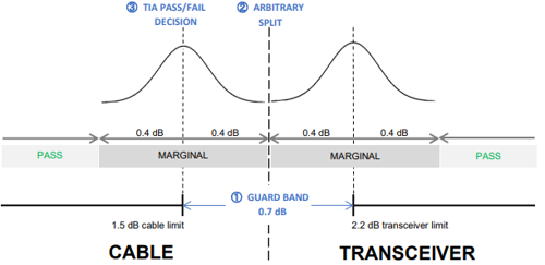
The problem, sometimes, is to test to the standard. For example, an 850 nm multimode MPO 40G 40BASE-SR4 system has a small transceiver to transceiver loss design limit of 1.5 dB. In some situations, 1300 nm cable testing is also required. The same system has a minimum transceiver loss capability of typically 2.2dB.
So, there is a "guard band" of 0.7 dB in the standard between the cable loss allowance and the transceiver sensitivity allowance. This "guard band" is real-world critical so the overall system works, while also making some allowance for test accuracy (of both cable and transceiver) and other limitations.
A "guard band" means we can accept marginal test results, if the uncertainty is within some limits assumed by the guard band allowance. One would imagine that in this case with 0.7 dB guard band between the cabling and transmission loss limits, then apportioning half of this to test uncertainty for each system, e.g. 0.40 dB (note a dB is logarithmic, so calculation is needed to convert linear things into dB things), would be a safe assumption.
One point on the "guard band" concept. Statistically, if 2.5% of either of the transceivers or cable systems are marginally worse than allowed for by the guard band, then the chance of these truly out of spec components getting mated is 2.5% of 2.5%, e.g. 0.06%, or one in 1,600 links. This concept seems to work well for us.
Generic loss test accuracy & confidence issues
This section is based on the "BIPM GUM Evaluation of measurement data — Guide to the expression of uncertainty in measurement" and explains why MPO testing is so problematic.
Test Uncertainty
The terms repeatability, accuracy, reproducibility or uncertainty are used somewhat interchangeably. For loss testing, there is little practical difference between them all, so we will use the formal term “test uncertainty”.
Quoted test uncertainty is always a ± value, and the exact way it is quoted matters. For example, a quoted test uncertainty of 0.1dB also includes ±0.149 dB. So, a limit of 0.10 dB is tighter than a limit of 0.1 dB.
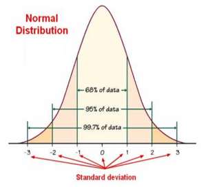
Test uncertainty is always quoted along with a "confidence level", which recognises that a % of test results will be outside the expected test accuracy. Statements of confidence level (or coverage factor) usually assume a normal / gaussian distribution and are stated in terms of standard deviation (sigma), percentage, or coverage.
1-sigma = 68.2 %
2-sigma = 95.4 %
3-sigma = 99.7 %
The default assumption for test uncertainty in our industry is a confidence level of 2-sigma or 95 %. In practice, this works fine for single fiber connectors (SC, LC, etc), e.g. 5 connectors out of 100 might have a test result outside the expected accuracy (too high or low). Note this is a test result outside expected accuracy, not necessarily a faulty component.
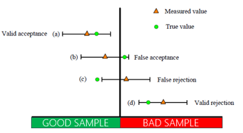
The "outside expected accuracy" statement is exact. If the measured loss is too high, it may create a false reject. If it is too low, it may create a false accept. Either is potentially "a problem".
However, if we then take a 12-fiber MPO connector, and a 5 % chance of any one fiber testing too high or low, then the 12-fiber array has a 12 x 5 % = 60 % chance of one test being outside expected accuracy. This is intuitively obvious: If I take 96 fiber ends of which 5 are randomly incorrectly tested, then (conceptually) rearrange them into 8 MPO connectors, then no more than 5 of the 8 (62%) connectors could have these fibers. Clearly not good, so the traditional "2-sigma" or "coverage factor of 2" or "95 % confidence level" assumption needs revising for multi-fiber connectors.
If we change our assumption to a test uncertainty of "3-sigma" or "coverage factor of 3" or "99.7 % confidence level" per fiber, then a 12 fiber MPO connector would have a 0.3 % x 12 = 3.6 % chance of testing too high or low. This appears much more appropriate. To convert a 2-sigma uncertainty to a 3-sigma uncertainty, multiply it by 1.5.
Passing and failing to a Standard
This section is based on TIA-568.3-D and the BIPM paper "Evaluation of measurement data –The role of measurement uncertainty in conformity assessment".
The cabling standard TTIA-568.3-D has many useful component and installation specifications and makes allowances for test lead losses. Section 7.3.7 describes how to calculate the attenuation allowance but does not mention any allowance for other test uncertainty.
All sections on test methods are "informative" only, not properly part of the standard, they detail test-set ups but do not properly discuss how to handle test uncertainty. It has a comment about handling of marginal test results is in Annex E1 "Attenuation measurement results should always be less than the designed attenuation allowance".
The BIPM paper goes into detail on how to pass and fail based on a measurement. It goes into the relationship between, for example: What is the relationship of risk sharing between an installer (cost risk of false rejection) and user (cost risk of false acceptance), the relationship between a design guard band, acceptable test uncertainty and test limits. It seems to exactly detail the situation we have, from a general viewpoint.
Test Equipment Accuracy
There is a very general rule-of- thumb as to what test equipment accuracy is needed to realistically achieve a reliable test results accuracy. This is called a "Test Accuracy Ratio" and for typical digital test equipment, a TAR of 4:1 is default. In other worlds, the test equipment accuracy should be four times better than the required results accuracy.
For loss testing on more traditional single-fiber connectors, both the test equipment and the practices have evolved to a point where it is usually not hard to achieve useful accuracy and results.
This is often not the case for MPO systems, partially due to the number of fibers per connector, and partially due to the typically small allowable loss. There are a few more factors: MPO connector loss is often less certain, and MPO test equipment is often lower accuracy than previous fiber testers.
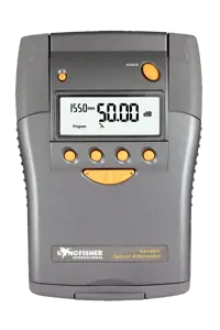
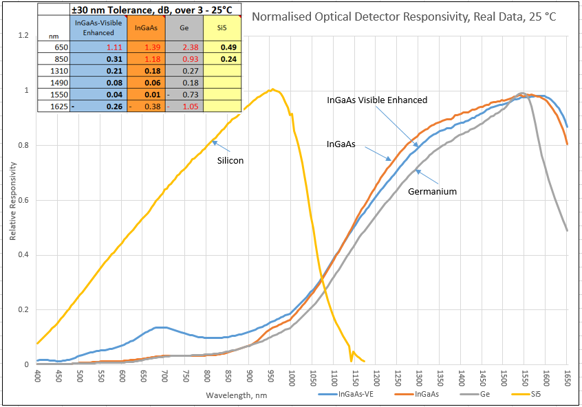
Below we show a graph of power meter response over wavelength. In the band 850 nm ±30 nm, with an InGaAs detector, a power meter response can vary by 1.2 dB just due to varying wavelength, with exactly the same power level. So, an InGaAs power meter cannot measure the power in our target 850 nm system with any great confidence.
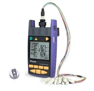
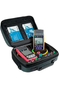
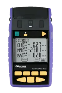
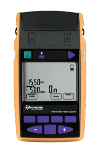
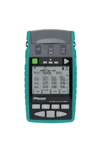
Here are specifications for four typical items of MPO test equipment:
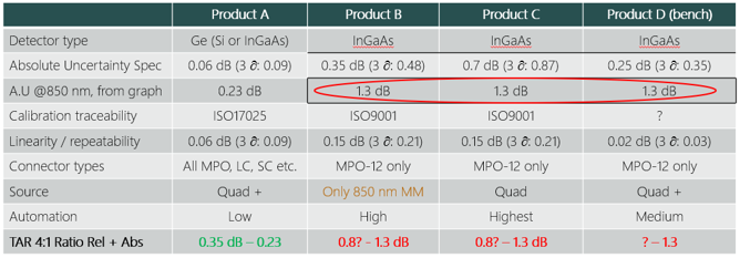
- Products B & C appear to use quite similar T&M technology and InGaAs detectors. They look like they would achieve comparable accuracy in practice, but their Absolute Uncertainty specs look different because they are under different conditions.
- Products B, C & D all use InGaAs detectors, which as we have seen, have an absolute power uncertainty of ±1.3 dB over a ±30 nm range in the 850 nm window. This dominates power measurements, but this spec is missing in their data sheet. We have used this spec as-is in the bottom line, it doesn't need multiplying by a TAR.
- For the linearity / repeatability / loss testing specification, we have calculated the 3-sigma value, and them multiplied this by the TAR (linear) to achieve the Relative number in the bottom line. It seems highly unlikely that Product D would meet its linearity spec at 850 nm, given its high wavelength sensitivity, so I have left this as a question mark.
- The bottom line represents the in-use accuracy you'd expect to achieve for both absolute and relative measurements with these products. Product A meets our 0.4 dB requirement, although it is less automated than the others, which do not meet the accuracy objectives.
- Most of these meters would struggle to perform the TIA standard patch lead verification check with a test limit of 0.3 dB.
- In practice, to achieve 3-sigma test uncertainty requires greater-than-usual care when performing testing.
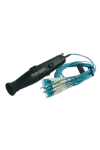
Test cords
Test lead performance is a major loss test consideration. “Elite” MPO / MTP leads are available with per connector / fiber loss of below 0.25 dB. These meet the TIA-568.3-D test lead verification requirement for a maximum loss of 0.3 dB per end for test leads.
Here are the USConec specifications for MPO connectors.
| Ferrule Type |
Random Mated Attenuation1
(≥ 97%) (dB) |
Mean Random Mated Attenuation (dB) |
Return Loss (dB) |
| Single mode Elite® |
≤0.25 2,3 |
≤0.12 2,3 |
≥60 |
| Single mode |
≤0.50 2,4 |
≤0.25 2,4 |
≥60 |
| Multimode Elite® |
≤0.25 |
≤0.12 |
≥25 |
| Multimode |
≤0.45 |
≤0.20 |
≥25 |
Per IEC 61755-3-31, predicted performance yield will vary at different ferrule fiber counts (e.g., For 12F, IEC Grade B estimated attenuation of 0.35dB with 93% yield).
Note 1: IEC 61755-1 defines Grades based on ≥97% random mated loss probability of channels meeting or exceeding loss specification.
Note 2: IEC 61755-3-31 is defined for up to 12 fibers for SM APC only.
Note 3: Exceeds IEC 61755-1 Grade B performance.
Note 4:Meets IEC 61755-1 Grade C performance.
Testing may need a combination of straight patch leads, and breakout leads. Also ensure that connector pin polarities are correct, since trying to swap these pins in the field is not usually viable. A few tested through connectors are also helpful.
Spare leads will be required in case one gets degraded or damaged. Some types of MPO connector are made so that a simple tool can be used to reverse polarity and add / remove pins. These seem very useful to escape from a test bind!
Some application environments have a mix of LC and multi fiber connectors. So naturally one might assume that LC – MPO breakout test leads are an obvious choice. However, SC – MPO breakout leads are typically more robust, easier to handle, and usually have better optical loss performance. SC-LC hybrid adaptors are easily obtained, however they need testing since many have inferior loss, so SC-LC adaptor leads may be a preferable choice.
Number the leads and ends A/B. Label through connectors so they can be identified, also label one end so the orientation can be maintained during testing.
Test cords require Performance Verification before each use. This performance verification test is quite specific, and failure to do this preliminary test may invalidate all the following test results. The basic objective of the performance test is to ensure that the loss of the cords meets the basic accuracy requirements.
- TIA-568.3-D requires a test lead verification loss of 0.3 dB or better.
The Test Cord Verification Test is quite simple: test each test cord connector using two reference cords, and the loss of the connection must be within the allowed limit. In the case of MPO connectors, this will take a longer due to the number of fibers.
Also, it may be preferable to note down the actual loss, repeat the mating & test a few times, and average the results to "calibrate" the test lead. These results can be subtracted from later measurements. This can improve test accuracy in some circumstances or is helpful if one fiber on the lead is marginal.
How to Fake Certification Results?
Sound contentious? But many folks are doing it: With a 60% chance of an erroneous reading per connector mating: just keep plugging up a connection a few times until it reads a "pass", then record that one. As well as covering for "bad" tests on actually good fibers, this process equally conveniently creates "good tests" on bad fibers. What is the value of "cable certification" if this is common practice?
Although "re-testing" is common T&M practice, at what point does it become "cherry picking" of nice-looking results?
The following four sections have been added for completeness, or just skip to the section "So, what loss test uncertainty can I expect?"
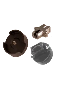
Inspection & cleaning
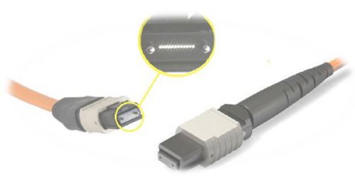
Connector condition and cleanliness is a major consideration and is the most common cause of problems. Absolutely essential are a good quality microscope with an MPO/MPT specific adaptor, a supply of suitable specific cleaning materials (more than one type is good), and adequate time and know-how to use them. The default available MPO cleaners tend to do a reasonable job of cleaning the fiber ends only, but extra cleaning materials should be available to clean alignment pins, and the whole connector end face.
Inspection and cleaning are performed on both ends, every time a connector is mated.
Cabling disturbance
Because of the combination of very low loss requirements, and fiber complexity, it is essential that testing and commissioning are accomplished with the lowest possible level of disturbance to connections. Also, once loss testing is done, any disturbance may require the loss testing to be repeated. This means that an unusually strict test commissioning regime is appropriate, so that each acceptance level is completed with exceptional confidence. You don’t want to go back in and disturb things. It is therefore sensible to break the work into distinct phases, where each phase is likely to result in less cabling disturbance, e.g.
- Get the cabling in place, with the right labelling.
- Check continuity, polarity, and end face condition.
- Test the loss.
Continuity testing
This is the most basic test: Does light get from end to end?
As a minimum, this test can be done with a VFL source and a one low quality breakout cable. If a numbered breakout cable is used each end, this could also double as a polarity test phase.
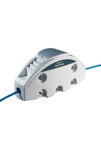
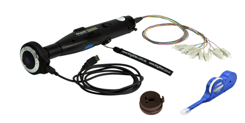
A fast & convenient way to achieve overall end-face inspection, continuity testing and polarity testing is with a Visual Cable Verifier
The continuity test phase is usefully accompanied by thorough cleaning and inspection of the connectors with a microscope. This achieves a few objectives. Bad connectors are the main cause of installation failures. Doing this here enables the installer to identify & replace bad connectors at the earliest (lowest cost) point. It also ensures that a bad connector does not contaminate the test leads and degrade other connectors.
If the connector quality is inadequate, there is little point proceeding to the next stage.
Simple continuity testing has one big problem: it doesn’t identify if fibers are swapped around. So, for this we talk of:
Polarity testing
Typically, the cable installation requires polarity testing, to determine that the correct 1 – n arrays of fiber at one end of a system, are mapped to the correct 1 – n arrays of fiber the other end. If the installation has a patching cable section so that connections can be split off to transmission equipment, niggling polarity mistakes can occur here. The polarity test needs a very high level of confidence, since if not 100% correct, there will be no chance of a working outcome, and a great deal of wasted work to find the swapped fibers. This will probably want a basic level of documenting, enough to record which fibers were tested, and the general array direction.
So, what loss test uncertainty can I expect?
For our target use-case (850 nm, OM4, 40G typical transceiver), we deduced that a test accuracy of 0.4 dB is desirable. It appears we can approximately meet this with the following precautions:
- Use phased install / test approach to minimize cable disturbance.
- Clean & inspect every time a connector is mated.
- Perform continuity / polarity / end face inspection.
- TIA “test limit = standards limit”, then 3-sigma test uncertainty is <0.4 dB.
- Test equipment needs 3-sigma accuracy specification.
- Test equipment needs 4:1 TAR (test accuracy ratio). Care will be needed on equipment selection.
- Use Elite level test leads, and perform test lead verification (0.3 dB).
- Use Encircled Flux source & mandrel for multimode fiber (0.12 dB, or 10% of loss).
- Enough time for testing, and training as needed.
However, once the test cords are plugged into presumably lower grade cords, the loss there could possibly jump to 0 – 0.5 dB.