So, you are making the move from testing copper Ethernet cabling, to testing Fiber Ethernet cabling. It’s another world, but here is broadly what to expect. If you never get around to any further formal training, at least read this much!
Overall cabling design issues
Installed copper cabling & equipment creates a significant electrical safety, fire and smoke hazard. Installed fiber cable only creates a passive fire & smoke hazard, so fiber cable safety is only about choosing a low smoke / fire retardant cable, and ensuring that fire stops are good. So some testing can be eliminated, and some key design issues no longer exist e.g.: earth bonding is irrelevant, and fiber cables can be laid right next to electrical power cables.
Fiber cable is typically smaller and lighter. However, to avoid signal loss or fiber breakage, care needs to be taken in verticals to ensure that the correct riser cable is used, and all bends need to be more gentle and controlled. At 850 nm, cables can take a hard bend before much light loss is apparent, but then they still may break after some weeks. One area of particular note is drop cables connecting to patching racks or equipment: the bend coming out of the back of the fiber connector should not be too tight, so long drop cables reaching high up in racks may need some additional cable support. The designer should specify the allowable bending radius for the selected cables.
The network designer usually specifies the required installation acceptance test requirements, however these may be more application specific than you are used to, as we will see.
Typically, fiber cable acceptance will be based on permanent link attenuation, length /signal delay, and connector quality. OTDR testing is sometimes done. Note that frame / data testing is not usually required at this level.
Multimode fiber transmission is typically fundamentally length limited due to signal dispersion or pulse merging, however since the length limit is often a lot longer than the size of the facility, length testing may not be needed. According to standards length acceptance can be “by inspection”. Single mode fiber is used for longer links, since it’s pulse dispersion is so low it can be ignored in this context.
Although fundamentally length is dispersion limited, in order to lower Tx/Rx equipment cost, a very tight optical loss may be specified, which creates significant optical testing challenges.
This discussion is about passive Ethernet optical cable, with optical connectors & separate transmitters. Where “active cable” is used, there are deliberately no fiber connectors, the fiber is hard attached to the Tx/Rx device, so no optical testing can be done.
Caution! Cable re-entry
Here is one of the great issues of the fiber world. Just unplugging and re-plugging an optical connector in a link can cause subsequent malfunction, most commonly due to microscopic dirt on connector tips. In other words, a “certified” link is no longer certified if it’s re-plugged. Optical connectors should be thought of as “demountable” but never “I’ll switch a few things around and have a play”. This sensitivity to re-entry should be borne carefully in mind during final rectification & testing, since any re-plugging will always require “re-test”.
This also means that you’ll probably want to prevent or minimize unauthorized access to tested cabling. This may be by using connectors that require a tool to remove, by using patching enclosures that have separate access to permanent link connectors, or by restricting general access to closets.
This also affects your acceptance work flow. You may want to follow a careful pattern of: inspect/ rectify labelling, then continuity / polarity test, then loss test, to minimise avoidable re-connection during the final phase.
Cleaning & inspection
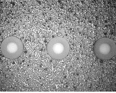
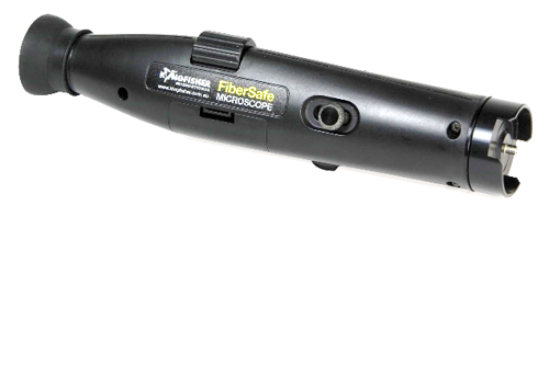
Fiber connector cleaning and inspection is an important new area which you’ll need to learn first up. Every time a connection is made, the connector tip should be cleaned and inspected prior to mating. Just get a good microscope, and a quick play with one will show you why. Most (totally avoidable) problems are caused by inadequate cleaning and inspection. This process will correctly take up a fair bit of site time, but is absolutely worth it. All technicians who make connections will need training and quick access to good cleaning & inspection resources.
On some jobs, it will also be a requirement to take pictures of connector tips and record these with your test results. “Automated pass / fail” inspection devices are available, but they are expensive, and the consistency is questionable. Sometimes it may be more practical to get hold of the visual standards, use cheaper equipment, and just make the visual pass / fail judgement yourself.
Whatever you do, make sure your staff get some practice with your chosen solutions so you can minimise site rework.
For Occupational Health and safety reasons, keep everything on site at a Class 1 power level by default. This means no more than 2 mW or +3 dBm emitted from any optical port, including any VFLs. Above this, you’ll need specialist laser safety knowledge.
Standards
For copper, you’d be used to standards being usually strictly followed by both equipment and cabling. You are used to a quite reliably mixing and matching equipment & cable, without too much regard for manufacturer or p/n. Oh, and we all know that cabling performance is very dependent on length and termination workmanship.
Things are different with fiber! Some fiber links only loosely conform to a standard, or conform to a defacto industry consortium arrangement. The default in some instances is to seek advice from the equipment manufacturer on acceptance testing parameters. In many cases, the equipment may have a plug-in fiber interface, so it’s actually the requirements of the plug-in interface device that you’ll need.
Certification, qualification, verification?
These copper-related words translate roughly as follows: Certification more usually describes staff technical training and approval. This aspect may not change too much for fiber: quality workmanship is the key.
A copper cable certifier is a (usually expensive) instrument used to test cabling to carry data conforming to a particular standard, typically e.g. 100M / 1G / 10G Ethernet data rates. This sort of testing may only loosely apply to fiber, as it doesn’t always have the same value here.
Qualification usually describes mid-level cable testing for a particular data use, e.g. a subset of a standard. You’ll note that this seems to regularly describe the fiber situation, although this term isn’t used much by the fiber industry. This may explain a lot of confusion.
Verification usually describes “craft tool testing” such as continuity etc. Fiber test tools also exist here, although they are quite different since it’s not really possible to “probe” a fiber cable.
Test equipment approval & acceptance
In the copper cable industry, it’s common practice for cable solution vendors to do laboratory testing on cable test instruments, and then write a letter of approval so these test instruments can be used to certify their installed systems (for warranty). This sort of equipment type approval just does not exist in the fiber world. So you have a wider choice of equipment. In the fiber world, it’s the personnel who are certified, not the test equipment.
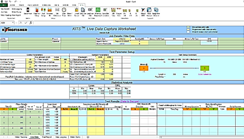
However, another common issue is securing the test data / report: it should not be possible to tamper with either the test results or the report. Use of equipment with insecure reporting software may lead to rejection of test results. Broadly, the test equipment needs to come with a complete & secure reporting package, or results are subject to the possibility of tampering. There is a very limited choice of solutions that meet this requirement.
These are the very broad issues. There will be other considerations such as: test wavelength(s), Encircled Flux compliance, and so on.
Test leads & wear
This is a subject to get your head around. If you have the best equipment and procedures, then test leads are probably the limiting factor on loss test accuracy, so they are important.
Firstly, test leads are a higher grade of connection, and they degrade quite quickly with use. So you’ll either need to buy such leads, or carefully test & select them out of a bigger batch.
Then you’ll need to keep an eye on usage, and replace them after around 1,000 insertions.
You should always perform a test lead verification prior to starting critical testing.
Test procedures
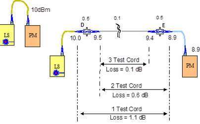
The TIA / IEC and other test standards require the use of one, two or three leads for source & meter referencing. There are typically various mixed objectives here:
- Test equipment connectors may not match the application. However, there are some tests where the power meter connector style must match the application, which may affect equipment choice.
- Fiber connectors are prone to wear-out, so the instrument connector is typically not used to directly test the cabling, to avoid degrading the instrument: the test lead serves as a disposable wear item.
- It’s possible that mixed fiber core diameters have been accidentally used in the system. A good test procedure should pick this up. You may note that more relaxed procedures are acceptable where there is only one fiber piece per link (no splices), e.g. this mix-up can’t happen.
- When OTDR testing, a test spool is usually specified after the instrument, or this length may be built into some instruments. You will also need to know how and when to change the various set-up parameters, in order of importance: the set fiber length must be longer than the link (or there will be strange ghosting effects), the averaging time should be “medium” for most approval testing, then the pulse width should be just long enough for test noise to be acceptable.
- When doing source and meter testing, make sure you understand how and when to take a reference.
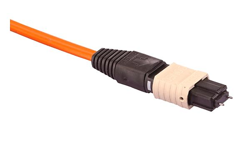
- Note that the standards usually require testing at 1300 nm on multimode fiber. This is to try and identify sharp bends which could cause later breakage. This may not show up at 850 nm, but may show up at 1300 nm. This has particular relevance to MPO connectors, since some MPO specific test equipment only tests one wavelength.
Test uncertainty
Surprisingly, Ethernet fiber systems typically have very tight optical loss budgets, which are a challenge to test. A lot of test equipment isn’t really good enough, so beware of:
Unstable light sources. When you nudge a connector on a source, or just reconnect it, best practice is that the connected power should typically not change by more than about 0.1 dB. Worse than this will cause problems.
Power meter detector types: Silicon detectors are best for 850 nm only, InGaAs detectors are best for for 850 - 1625 nm.
Power Meters with a small detector and no optics: for a simple power meter head, a 1 mm diameter detector is very poor: 3 mm is best. These small detectors are just inaccurate, since some light misses the detector, so they are sensitive to beam geometry.
Broadly, test uncertainty goes a bit like this: Your acceptable maximum loss is say 1.9 dB, and your test uncertainty is say 0.5 dB, so any loss test result over 1.4 dB is marginal. That’s tight! Obviously any reduction in uncertainty will be welcome, which will require a combination of good equipment, good test leads, good test method, good attention to cleaning & inspection, and so on. A weakness in any of these may have a serious impact on this common scenario.
“Marginal Test Results” in this situation are a significant issue. More usually in T&M, the expectation is that marginal results are a very small % of tests, the % uncertainty is quite small, so traditionally in the electronics industry standards, marginal results are accepted. However, in this situation almost none of this is true, so the situation needs serious consideration. Many testers in this situation just reject or retest anything marginal, on the basis that they do actually want all installed systems to work properly. From the above, you can see why devotion to test accuracy is required for fiber LAN testing.
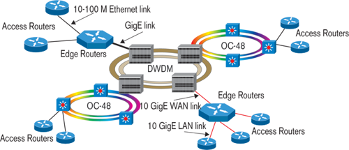
Some typical fiber ethernet scenarios
At the time of writing, 10G and 40G deployments are becoming common, and 100G deployments are just starting to take off. A partial listing of popular fiber Ethernet deployments:
10G Base-SR: 850 nm, OM3, LC, Max loss / length: 2.6 dB /300 m
10G Base-L: 850 nm, SMF, LC, Max loss/ length: 6.3 dB / 10 Km
40GBASE-SR4: 850 nm, OM3 or 4, MPO-12, Max loss / length: (1.9 or 1.5) dB / (100 or 125) m
40GBASE-FR: SMF, LC, Max length: 2 Km
40GBASE-LR4: nm, SMF, LC, Max loss / length: 6.7 dB/10Km
100GBASE-SR10: 850 nm, OM3 / 4, MPO-24, Max loss / length: (1.9 or 1.5) dB / (100 or 125) m
400G: standard in progress
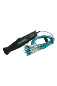
So, what do I need for LC & MPO testing?
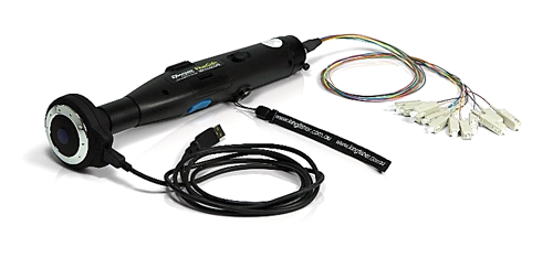
Anything to do with LC connectors is relatively easy compared to MPO / MTP. The problem with MPO connectors is that test solutions are currently uncommon, prices can be very high, performance can be well below both expectations and requirements, and there are just so many fibers to test that test throughput & confidence can be a real issue.
At the “high end”, there are various attractive looking MPO specific cable test solutions which should offer very good test throughput, however their technical measurement performance is often quite poor, resulting in a lot of re-testing and frustration. These solutions are also typically tied to only one test wavelength, and only one connector type (e.g. 12 x 1 @ 850 nm only). At the “low end” are any standard sources and power meters, however their throughput is just too low. A mid-level solution comprises MPO-optimized power meters, so that the power meter end doesn’t need moving as each fiber is tested, which greats speeds up & simplifies this procedure. This mid-level solution is easily adapted to a wide range of fiber types, wavelengths and fiber counts.
- Cleaning materials. For LC this is easy, MPO is a bit more difficult, since some solutions do not seem too good, or need too much care in use. Each technician needs these consumables.
- Inspection Scopes: Each technician should have “something”, which could be an inexpensive optical scope, and some may want electronic scopes with more capability. Good MPO scopes are less common.
- Test Procedures to go with your equipment, including a Test Lead Check.
- Test Leads, and a test lead maintenance plan.
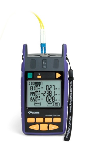
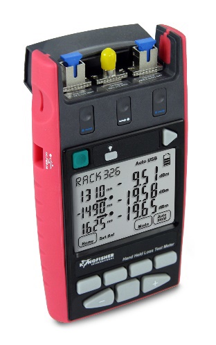
- Loss test equipment with excellent accuracy / stability, and secure reporting software.
- Power meter ports should preferably accommodate duplex LC connectors.
- Test sources should be Encircled Flux compliant, or use a suitable conditioning lead.
- Some way of arriving at “cable length” which could be “by inspection”, or with some other length tester, or with an OTDR.
- OTDR and launch spool when specified.
- Try out the test procedure & equipment in a test environment before going on-site, early enough so that you can rectify obvious equipment deficiencies.
- Send a sample report (format) for general approval by your customer.
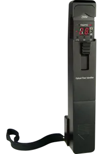
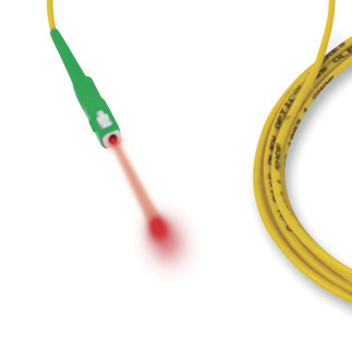
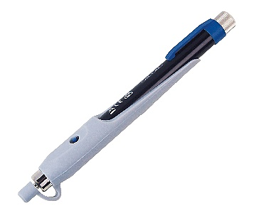
- Craft tools such as a VFL for fault finding / identification / polarity testing.
Test flexibility
Commonly, cable crews work on many systems, and a lot of time can be lost if different equipment needs to be learned for each system. Common sticking points are:
- Connector styles: can your gear handle a good range conveniently? What about other MPO like 24 fiber etc.?
- Wavelengths: can your equipment work with a range of requirements?
- Fiber Types: Both Single mode and Multimode?
- Reporting: How many customers can be supported with one reporting solution? Service provider and Enterprise? That can save a lot of learning!
- Accuracy: how much uncertainty is acceptable for a higher end system?
- Future Standards: Is the gear likely to still be relevant in future? How can it work with new standards in future?