Introduction
Any optical transmission system requires a defined range of optical receiver input power for proper operation. In practice, the received power must be higher than the minimum level and lower than the maximum level. The difference between these power levels is the optical margin.
When a transmission system is designed, consideration is given to expected transmitter power, receiver sensitivity, and link loss. The link loss budget is then planned so that there is some extra power at the receiver to allow for degradation over the life of the system, or alternatively the receiver power level should not be too high. For reliable operation, it is important to verify that this planned margin is achieved, otherwise repair and maintenance will be difficult, expensive, or impossible.
A design margin of 6dB is common in telecom systems, although the installed system may achieve a better value, since "worst case" conditions are of course infrequent. The design margin of some high-speed LAN systems may be much smaller, since these systems are typically limited by chromatic dispersion rather than loss.
A variety of factors may impair transmission. For example, in high-speed systems, polarisation mode dispersion (PMD) or chromatic dispersion (CD) may limit transmission performance. In slower systems, performance is usually limited by optical attenuation.
In some situations (notably analogue systems), it may be a design requirement to insert a permanent attenuating pad to optimise the power level coming into the receiver.
Margin verification
Margin verification can save money during construction: If the overall margin is achieved as required, then expensive re-work of sections that are outside planned specifications can be avoided.
Margin verification is one of the final tests on an installed transmission system.
To measure optical margin, the essential apparatus is:
- A complete and operational transmission system.
- An instrument to measure transmission quality. For instance, an instrument to measure Bit Error Rate or BER, or a signal / noise meter depending on the nature of the transmission.
- Some fiber optic measuring instruments:
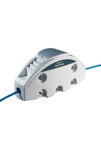
A Variable Optical Attenuator (VOA) to adjust the attenuation. This must have sufficient power handling capacity, it's optical characteristics must not degrade the transmission, and it should be accurate at the operational wavelength(s).
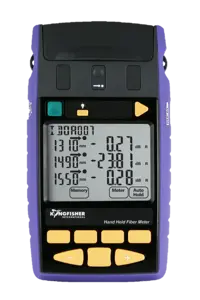
An Optical Power Meter to measure the absolute light level, which must be accurate at expected power levels and wavelengths.
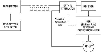
The BER test fiber optic approach is similar in most cases:
- Establish that the system is operating as planned.
- Insert the adjustable VOA into the system, and gradually change the attenuation until the Bit Error Rate (signal quality) is marginal.
- The extra attenuation introduced by the VOA at the point of marginal operation, is the margin value.
- Measure the power level going into the receiver.
During these BER tests, it is important that the VOA used does not cause any additional signal degradation. The Kingfisher VOA meets this criterion, since the instrument's back reflection, PMD and PDL are so low that the attenuator can be used in virtually any situation without regard to additional signal degradation.
It is important that achieved margin is not confused with measurement uncertainty. Therefore, the margin verification should be performed in as accurate a manner as possible. For example, if the measured margin is 5 dB, but the overall measurement uncertainty is 2 dB, then in fact the margin may be only 3 dB, which might be unacceptable. It could also be 7 dB, which might be acceptable.
Kingfisher VOA
The Kingfisher VOA provides various benefits to improve the productivity and effectiveness of such measurements:
- The in-circuit attenuation is accurately calibrated and displayed and is insensitive to wavelength.
- The correct connector for the job can be installed with the interchangeable adaptors.
- The use of either step or program modes enables the user to speed up the job, with less skill.
- Multimode attenuators have 62.5 or 50 u fiber options.
More information