Introduction
The optical power distribution across a multimode fiber core causes optical attenuation to vary. It also affects the transmission bandwidth and noise of an operational system, although this is outside the scope of the following discussion. Recent interest in use of multimode fiber at data rates above 100 Megabaud has made this a major issue, and during 2003/4, various ideas have been embodied in standards updates which determine the way an optical LAN should be tested. This paper summarizes the current situation for attenuation measurement applications.
Modal distribution
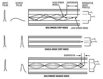
Multimode light transmission is by many different paths (see Fig 4.2).
The paths (or modes) nearest to the axis of the core are called low order modes, and the paths with the most deviation are called high order modes.
It is the high order modes that get attenuated (lost), and as they do so, light gradually transfers from the lower to the higher order modes. Interaction between light in the various modes causes some level of random signal noise, which is called "modal noise".
When light is injected into a core, initially the relative proportion of light traveling in low or high order modes will depend on how the light was injected.
- If an abnormal amount of light is in the low order modes, the core is "under-filled", and losses will be abnormally low. This situation is commonly achieved with a laser emitter. This situation also minimizes pulse spreading due to modal dispersion. Various multimode transmitters used this effect to transmit dater at a higher rate than the "bandwidth rating" of the fiber being used.
- If an abnormal amount of light is in the high order modes, the core is "over-filled" and losses will be abnormally high and may appear "out of specification". This situation is commonly achieved with an LED emitter. In this situation, signal pulse dispersion will be worse than expected from the fiber bandwidth specification.
- After typically 1-2 Km, the relative distribution of modal power stabilizes and is independent of the initial launch condition. This condition is called an equilibrium mode distribution, and is the condition traditionally used to measure individual multimode components. This is interesting, but usually irrelevant to today's multimode systems where most link lengths are much shorter than this. The concept is a remnant of a long past era when multimode was used in long distance Telecom applications.
If attenuation tests are made without first establishing a known modal distribution condition, then the attenuation results obtained will be unrepeatable. It should be noted that performance specifications of multimode systems are only valid for a specific mode condition. In other circumstances, different characteristics will be measured.
So, to perform meaningful multimode measurements, it is necessary to first define the modal distribution condition.
Recent standards change the emphasis in multimode plant verification. The traditional approach was to try and measure at an equilibrium modal distribution, eg an average result. The new approach uses an over-filled source, e.g. worst case result. The new approach also matches the conditions found in practice in today's short distance applications using a LED transmitter.
Of the two types of multimode fiber in common use today, the new standards appear to concentrate on 50/125 OM3 fiber. In fact, a source that is fully CPR compliant with this type, in our experience may not be CPR compliant with the older 62.5/125 types. Presumably the standards folk will resolve this issue in due course. This incidental anomaly is probably a by-product of the fact that CPR issues primarily focus on CPR and its effect on bandwidth, rather than the secondary issue of attenuation measurement.
Use of a mandrel-wrap or mode stripper cannot create something approximating to a modern overfilled launch condition (a common misconception). This must be achieved with a suitable compliant source.
Coupled power ratio CPR.
CPR is the numerical ratio between the power in a multimode core, and the power coupled to a single mode core when connected to this multimode core. It quantitatively defines a modal distribution condition. It may be expressed directly in dB or more typically as a numeric category between 1 (overfilled) to 5 (under filled). There is currently good agreement between standards bodies on CPR. The CPR concept is easy to implement. It is a relatively simplistic version of a near field measurement, or beam profile measurement, which are hard to test.
For example, if the power in a multimode core is -21 dBm, and the power coupled from that core into a single mode core is -41 dBm, then the CPR is 20.
The new standards define that the default source for multimode plant should be (overfilled) Class 1 CPR, with a defined wavelength spectrum. So, a properly characterised LED is the preferred source, and measured attenuation values will be worst case.
Whilst easy to comprehend and implement, it is understood that CPR does not adequately define the beam geometry in all cases, so further work is currently under way to devise another method. Modal Power Distribution (MPD) and Encircled Flux are two ideas currently being investigated for this purpose.
Mandrel wrap
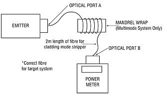
A mandrel wrap is typically five turns of multimode patch lead around a mandrel. It is used to strip off very high order "edge" modes, which are unstable and cause measurement instability. Use of both a defined CPR and a mandrel wrap achieves best repeatability. The fiber type should match the application.
Note that in this arrangement, a mandrel wrap does not significantly affect the CPR, it just strips off edge modes. Failure to use such a mandrel wrap affects measured results by making them a bit more variable.
Class 1 CPR and a mandrel wrap attempt to replicate, in the field, the launch condition used in the factory (defined by FOTP-50B) for qualifying attenuation and connector insertion losses, thereby providing field measurements that more directly relate to manufacturer's specifications. This allows users to better assess the quality of their networks.
The standards define a mandrel wrap as being 5 non-overlapping turns of cladding mode stripping fiber. The diameter depends on the core diameter and standard being followed. For 62.5 u there is good agreement that the core should be on a 20 mm diameter (the mandrel may be a different diameter depending on the sheath thickness, up to 3.5 mm). For 50u cores there is currently total disagreement, the Europeans stating 15 mm, and the USA opting for 25 mm.
More information