Introduction
This note explores the strengths & weaknesses of OTDRs and loss test sets, since they are often used in similar situations. A loss test set may be a light source and power meter pair, or an integrated OLTS.
Deciding factors are often to do with:
- Labour expense. An OTDR meter requires much more technical expertise and training to use, and any OTDR testing procedure is generally much slower. So, the labour expense of using an OTDR may be considerably higher. Expert labour to operate an OTDR may not be available in the required timescale, when a simpler loss test set can be operated faster and with lower skill levels. An OTDR may have a hidden expense due to the cost of training and the requirement to keep specialised technical staff available on call, for the operational life of a system. The message here is simple: where possible, use instruments that require modest skill levels and a minimal number of personnel.
- Asset expense. The "Total Cost of Ownership" of test equipment includes many (often larger) factors. For example, suppose a meter cost US$ 700, the batteries are changed weekly costing US$ 208 a year, and it is calibrated yearly at a cost of US$ 200. So over 5 years this $ 700 instrument has cost $ 2,740. If re-chargeable batteries are specified, then the cost in labour and management may be higher. There is also the issue of asset availability, e.g. an OTDR is a more complex instrument which may require a fair bit of down time for calibration, firmware updates, maintenance etc. In contrast, a loss test set often costs a lot less over lifetime and can usually be repaired or calibrated quicker. A loss test set can often be used on a wider variety of systems than an OTDR.
- Test Requirements. A given installation job may specify which sort of test is needed. Quite often (e.g. TIA 568.3-D), a loss test is required and an OTDR test is optional.
- Administration expense. This is often a hidden factor, but includes, for example: Managing the asset inventory life cycle, producing customised acceptance reports for clients (which can take longer than acquiring the data), and the general ability to complete jobs on time with minimal project management overhead.
- Corporate risk management. The company must be able to show appropriate due diligence in situations where customers have suffered or may suffer severe penalties or loss of customer confidence in the event of a system outage. These financial consequences generally greatly exceed the total T&M budget. So it is merely good business logic to ensure that T&M processes are performed correctly.
How does an OTDR work?
An Optical Time Domain Reflectometer is essentially an optical radar: it sends out a flash of bright light and measures the time and intensity of the echo or reflection. This weak signal is averaged to reduce detection noise, and computation is used to display a trace and make several mathematical deductions.
What is a fiber optic OTDR best used for?
An OTDR fiber tester is good at measuring distance and point losses on installed systems, so it is used to find faults and measure point losses such as caused by splicing. However, to do this accurately is more complicated and time consuming than is commonly supposed, since a measurement should be taken from both ends of the system, and then averaged. If this is not done, spurious excess losses and "gainers" may be recorded where different fibers are joined, resulting in wasted splicing effort while non-existent faults are "repaired". This is a particular issue when measuring the fusion splice joints, where the loss is small, and the adjacent sections may have fibers with different intrinsic backscatter characteristics.
OTDRs can be used for return loss measurements, although quoted accuracy is not very high.
Who is likely to use an OTDR?
An OTDR is most used during installation acceptance and maintenance of outside plant cables. In this role, it is likely to be used to identify point losses, the length of various cables, and to measure return loss.
OTDR Limitations:
- Setting up an instrument and interpreting the trace requires too much skill for many technicians involved in approval testing of new systems. These people must rely on built in automation to compile data tables. However, this automation is not always reliable, so these users can get into major difficulty.
- Use for fault finding typically requires a more skilled operator who understands how control the measurement process in detail, and also interpret the trace accurately.
- Because of the skill requirements, most organisations end up with a small number of identified "experienced" operators, who train others, and are called out to problem situations.
- It may have surprisingly limited ability to separate multiple point losses that are close together. This problem happens quite regularly in practice, due to the "dead zone" effect. Although instruments may advertise an event dead zone of say 5 m, this is only under optimal short-distance test conditions with low reflection connectors. Multi-mode systems usually see a longer dead zone than specified due to reflective connectors. In practice the dead zone may be a km for long distance work. Other tools, such as a visible laser, may be required to precisely identify the fault. This has become a big issue as the fibre count in cables has increased, which has caused an increase in the requirement to avoid disturbing already installed closures and racks.
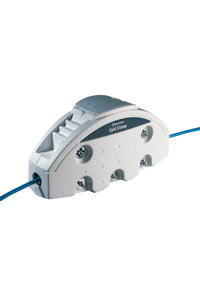
- The distance measurement accuracy is only about 1 - 2 % at best. For example, a displayed result of 12.1567 Km is actually more realistically 11.91 - 12.39 Km, an uncertainty to field staff of nearly half a Km. The reasons for this are fundamental and are due to variations in cable manufacture and index of refraction. So, a measurement of 1 Km, is typically not 1 Km of cable, and certainly not the exact route length. Use of a Cold Clamp can greatly improve distance accuracy.
- Limited accuracy when determining the end-to-end loss of a system. It typically makes a poor job of measuring the loss of the end connectors, which are themselves a common cause of problems.
- Limited use on "passive optical network" systems that use couplers or splitters to connect one source to multiple locations. This is because measuring in this configuration only works in one direction, and so this method cannot be reliable.
- Cannot be used in compliance with some multimode fiberoptics loss measuring standards, which mandate the use on an LED source with defined characteristics.
- Accidental connection to a receiver can damage the receiver due to the high instantaneous power levels. There can be some optical safety issues associated with the high pulse powers in these instruments, which often exceed +20 dBm.
- Factors to look for are now typically ease of use, quality of automation program, good local support, and compatibility with previously acquired measurement file types.
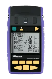
How does an LTS work?
Optical loss test sets incorporate a stable source and a meter. Measurements are made with a two-stage process. First the source power is measured (referenced), then light is put through the device to be tested, and a second measurement is made. The difference in the measurements is the device loss.
What is an LTS best used for?
- A pair of these units can be used to simply and reliably measure end to end loss of installed systems, preferably using a bi-directional or two-way method at multiple wavelengths, with minimum inventory and modest technician skill levels.
- There are a wide variety of LTS, with wide differences in resulting productivity. The simplest are just a source and meter in one box. The most sophisticated perform automated bi-directional, multi-wavelength loss and return loss measurement in a few seconds.
- LTS are easy to use. In most organisations, many technical staff could perform a loss measurement.
- Most LTS can be used to measure the absolute power of a transmitter or receiver, and some can be used as a tone transmitter or detector.
- If the LTS measures return loss as well, the requirements for optical TDR evaluation may be eliminated in some cases.
- Some LTS provide the simplest possible solution of all types since their automation makes them less complex to use than a separate source and meter.
- A single LTS instrument may be cheaper than a separate source and meter, and so may be a cheaper solution in some cases.
Who is likely to use an LTS?
These are widely used by almost everyone involved in hands-on work, since it is the simplest way to ensure that connections are up to standard. Used during work on component manufacture, equipment manufacture, cables and transmission systems. In this role, it is used to to formally accept end-to-end loss specifications, and sometimes to measure return loss.
LTS Limitations:
- An LTS cannot identify the position of a point fault in a route that otherwise passes the end-to-end loss specifications. For this reason, both OTDRs and LTS are often used for acceptance verification.
- In some situations, it is cheaper and easier to use a separate source and meter.
- Specific instruments may have limitations to do with accuracy, warm up periods, battery lifetime and ease of use.
- An LTS should have some sort of automated wavelength synchronisation for measurement at multiple wavelengths. Not all units have this useful feature.
Sources and Meters perform the same functions as an LTS, however with greater flexibility since a single source and meter pair can also be used each end of a link.
Who is likely to use a Source and Meter?
This performs a similar role to an LTS, with the advantage of great flexibility, and the disadvantage of increased inventory and slower operation. Transmission personnel may use a meter on its own to measure the absolute power of transmitters and receivers.
Source and Meter Limitations:
An LTS may cost less to own than a separate source and meter.
Specific instruments may have limitations to do with accuracy, warm up periods, battery lifetime and ease of use.
Source and meter combinations that don't have some sort of automated wavelength synchronisation will be harder to operate.
How much integration is desirable?
Instruments are available with different levels of integration. It is possible to buy OTDRs with built in source, meter, visible fault finder, talk set etc. However, is this desirable? The answer to this is "often not". It depends on:
- Productivity. Simpler-to-use testers may be more productive and less prone to error.
- Overall asset cost. It may be much cheaper to buy a few OTDRs and a lot of loss test sets.
More Information
You may print, photocopy and redistribute this document for educational use only, provided that this page is printed as is, without modification. This page may not be used commercially.